Showing posts with label 1990 - Three-Five Systems. Show all posts

De Dietrich LED Control Panel

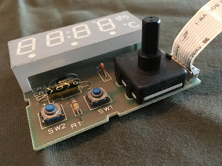
Another display module design that I put together was for the French company De Dietrich, who  manufacture high end cooking equipment, and this module was intended for an oven.  The module required an LED display with custom icons, two switches and a rotary switch encoder.

The completed module

This module comprised two designs, the LED display module and the main board it was mounted to.  The LED module consists a printed circuit board and custom plastic molding.  The custom molding includes a flame icon and a celsius symbol.

The icon is top right of the module

As with other Three-Five designs, the LED controller die was bonded directly to the custom LED PCB.  Three-Five Systems had extensive experience with wire bonding, as all LED displays require wire bonding.

Sadly I cannot find a picture of the display in the final unit, so if anyone has one, please feel free to send me a copy. 

Industrial Controller Display

This was another industrial controller display, that was to fit into a quarter DIN enclosure. However I cannot for the life of me remember who the customer was.

The module was to fit in a quarter DIN enclosure, and comprised a custom plastic molding.for the display, and a printed circuit board.  The display chip was a National 5450 as was used in many Three-Five modules.

The four switches were I believe soft switches and were just routed back to the main board.  All in all, a very compact design.

Lenze Industrial Inverter Display Panel

This was one of my first LCD designs.  Again I was responsible for the electrical, PCB, LCD and mechanical designs. This was a custom LCD display that was to fit into a plastic molding.  The LCD was a separate custom design that I put together including the metal bezel.

Custom LCD module on the main assembly

The electrical design for this was a little more complex.  Back in the 90s the LCD was driven but both X and Y drivers, mounted in die form under the LCD PCB.  The LCD itself was a custom design completed on AutoCad and manufactured by Three-Five Systems.

Completed Assembly

The remaining electrical design was conventional surface mount tech, as can be seen in the photos of the completed unit.  Some push buttons and LEDs completed the design.

The Complete Unit in situ

And this is what it looks like in the finished unit.  The module was designed for a number of different units, this is just one of the 

Bang & Olufsen LED Bargraphs

Bang and Olufsen are a Danish audio company known for their very high end design. This was one of my first designs at Three-Five. The design itself is quite simple, but the complexity lay in the wire bonding. To get the design just right, some of the bonds had to be as long as 4mm.  This is a very long wire bond and getting that wrong can lead to low production yield.

Green and Red LED Bargraph


Some very long bond wires

The good news was the factory was ok with the bond wire length and the units went into production.  What I wish I knew is what system these went into.

Custom LED Dot Matrix Display

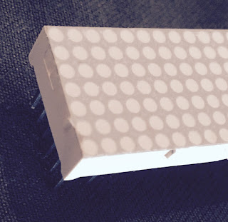
This project was a stackable LED dot matrix display.  I don't have the drawings for this any more but this would have been about 25mm x 100mm (or 1"x4" for my American friends).  For this design I was again responsible for the electrical design, PCB layout and plastic molding design.

The Display Module

In order to make this stack correctly, the plastic molding had indents and protrusions to ensure alignment.  The photo below shows this detail.

This shows the location lugs

The electrical and PCB design featured a bank switched LED array, driven by a National 5450 LED driver, with the die directly mounted to the PCB (the black blob shown below) so part of the PCB design included the die layout and bonding diagram for the die placement. 
 
LED driver on the board

I believe this was in red but as for the purpose of the display, that is lost in the mists of time.

The structure of an LED

During my time at Three-Five Systems I worked as a design engineer.  My role was electrical, optical and mechanical design.  As such I learned a lot about the structure of LEDs, and how to design an LED display.  Here is a little about that.

LED Structure

The first thing most people don't realize about LEDs is that they emit the majority of light from sides not from the top. In fact the top of an LED is where the bond wire connects.

LED Assembly

This means that to maximize the light output of an LED segment, the plastic molding needs to have a polished internal surface, and be angled to reflect the light towards the top of the molding where the diffusion layer is.

The diffuser is the layer of thin sheet plastic on the top of the plastic molding.  It diffuses the reflected light from the LED to create a uniformly bright segment.  If there is not enough diffusion, the LED can appear as a bright spot in the segment and thats poor quality.

LED, PCB and plastic assembly

LED Brightness

A DC current through the LED will provide a constant brightness.  The brightness being in direct proportion to the current. More current = more brightness.  However there are limits, namely thermal destruction!  An LED has some resistance to current. That resistance will produce heat and as the current goes up so the heat dissipated by the LED goes up until eventually a limit is reached and LED breaks and stops working.

By using Pulse Width Modulation (PWM) techniques, we can reduce the current through the LED, while appearing to increase the brightness.  This is because of something the eye does called integration.

If we have a high enough frequency for the PWM, the eye will not see the LED flashing, but sees it as a constant source of light.  If we take 2 LEDs, and one we provide a DC current of 10mA. The other we provision with 20mA with a 50% duty cycle, both are using 10mA average but the PWM LED appears to be brighter. 

Getting it all Even

So we have our LED bonded to our printed circuit board. We have a plastic molding that is shaped to reflect the light from the LED upwards to the top of the LED well.  To even out the light we add a diffusing film over the top of the well.  This does two things; it evens out the light distribution reducing bright spots in the LED segment, and it protects the LED assembly from damage and ingress of dirt and other foreign particles that may prevent operation of the LED.

There is of course a lot more that can be written about the structure of an LED segment, but the purpose of this post was to cover the basics and I think we achieved that.

ABB Industrial Controller Display Panel

I worked at Three Five Systems for five years.  I was the only engineer in the UK office and in my time there I did the electronic design, PCB layout and the plastic molding design.

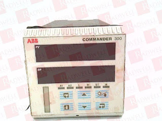
This assembly is the front panel for an industrial controller.  It consisted of 6 dual digit displays (14 segments), and a bar graph module. Both of these modules are custom assemblies, so I had three PCBs and two plastic moldings to design.
the complete assembly

The electronics to drive all of this consist of discrete transistors for bank switching, National 5450s for the LED driving, (remember this was the early 90s) and a couple of voltage regulators.

The PCB back side

I used PCAD to perform the PCB layout, and AutoCad for the plastic moldings.  However, to create these modules, Three-Five would use the silicon die and wire bond directly to the board. In the picture above, the black blobs are where the die is located.

The completed Module

I can't find a decent picture of the completed module, but here is a watermarked picture of the module.